Earthing System Design Basics: Why IS 3043 Matters for Industry
What earthing actually does, how IS 3043 approaches design, and the earthing mistakes that turn up most often on industrial sites.
- 5 min read
- 3 sections · 3 FAQs
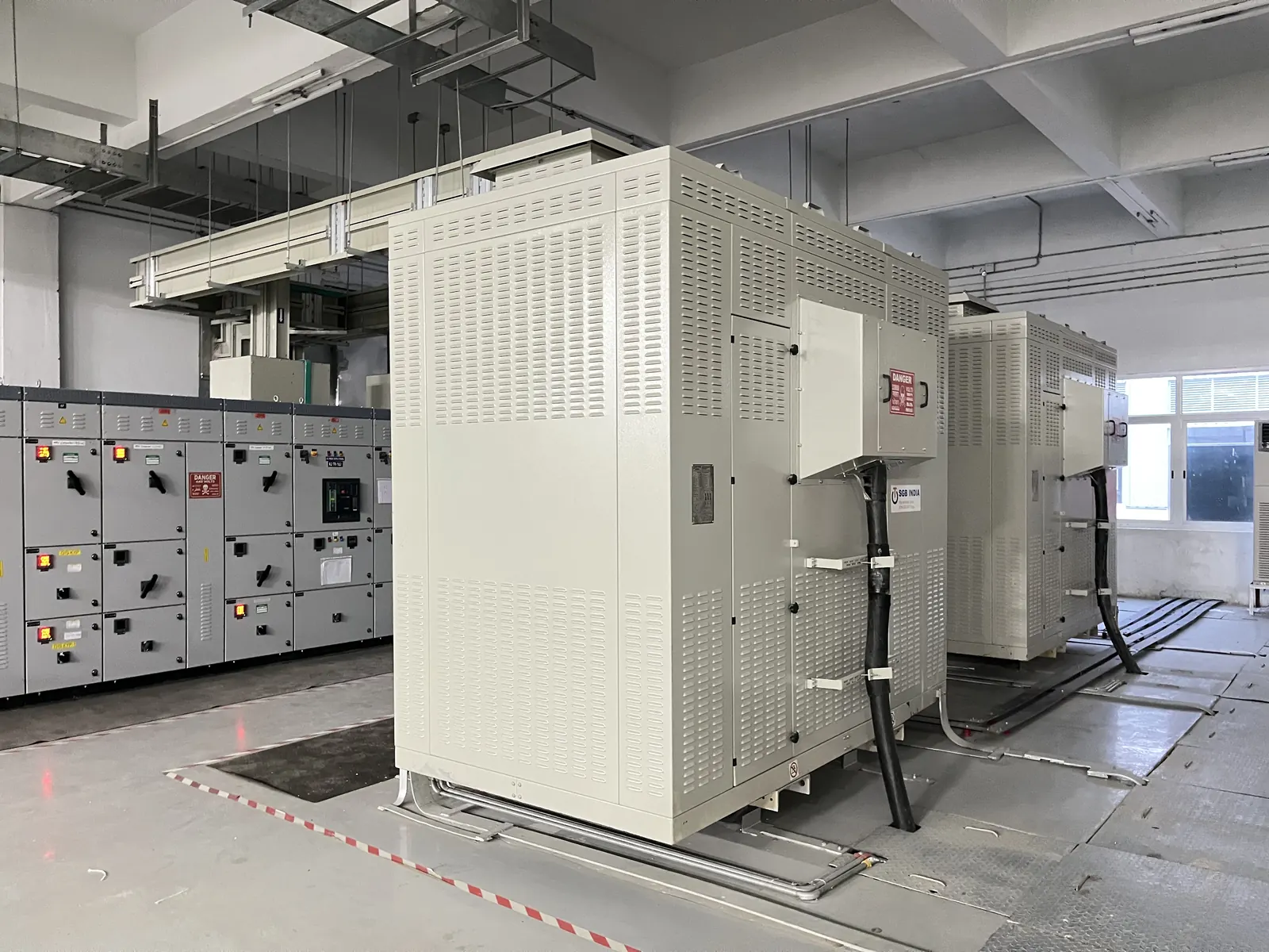
Earthing is one of the least visible parts of an electrical installation and one of the most important. When it is designed and maintained well, nobody notices it. When it is not, the results range from nuisance tripping and damaged electronics to dangerous voltages on equipment that people touch every day.
In India, IS 3043 – Code of Practice for Earthing is the main reference for earthing design, and the CEA safety regulations require installations to be earthed. This article explains the basics for plant engineers and facility managers: what earthing does, how IS 3043 approaches design, and the mistakes we see most often on industrial sites.
What earthing actually does
Earthing has three jobs: limiting the voltage that exposed metalwork can reach during a fault, providing a low-impedance path so protective devices operate quickly, and holding the system voltage stable relative to earth. It is usually discussed in two parts.
System earthing
System earthing connects a point of the power system, normally the neutral of a transformer or generator, to earth. It fixes the system voltage relative to earth, helps control overvoltages and determines how much current flows during an earth fault. The earthing arrangement (such as TN-S, TN-C-S or TT) and whether a neutral is solidly earthed or earthed through a resistor are design decisions with direct consequences for protection settings.
Equipment earthing
Equipment (protective) earthing connects the exposed metal parts of equipment, such as panel enclosures, motor frames, cable trays and structural steel, to the earthing system. If insulation fails and a live conductor touches an enclosure, fault current returns through the protective conductor and the breaker or fuse disconnects the supply. Equipotential bonding of metal services such as water pipes, gas lines and building steel keeps everything within reach at a similar potential.
Designing to IS 3043
IS 3043 covers earthing for power systems, substations, buildings and special installations. A sound design for an industrial site starts with measurements, not assumptions.
Soil resistivity testing
Soil resistivity varies widely with soil type, moisture, temperature and depth, and the same site can give very different values a few metres apart. Measurements are usually taken with the Wenner four-electrode method at several spacings and in more than one direction, ideally in the drier months. The results show how deep and how widespread the electrode system needs to be.
Electrodes, conductors and pits
Electrodes may be pipes, rods, plates or buried strips, used alone or as an interconnected grid. Conductor sizes are chosen for the prospective fault current and its duration, with an allowance for corrosion. Each earth pit should have an accessible inspection chamber and a test link so the electrode can be disconnected for measurement. Copper and galvanised steel both have their place, but mixing them carelessly invites galvanic corrosion. Where chemical earthing compounds are used, they should supplement a sound design, not replace one.
Target resistance values
There is no single earth resistance figure that is right for every installation. The required value depends on the system voltage, the earthing arrangement, the prospective fault current and protection clearing times and, for HT substations, on keeping touch and step voltages within safe limits. A small LT installation, a factory substation and a lightning protection system will each have different targets. Your design engineer should set them by calculation and record them, so periodic tests have something to be compared against.
Testing, lightning protection and common mistakes
An earthing system is only as good as its last test and its weakest joint. Common mistakes we find on industrial sites include:
- Isolated “clean” earths for electronics or instrumentation that are not bonded to the main earth.
- Earth pits buried under concrete or paving, with no access for inspection or testing.
- Undersized or poorly terminated earth conductors and corroded joints inside pits.
- Neutral and protective conductors combined or swapped where the design keeps them separate.
- Adding electrodes to chase a resistance number without checking the actual fault path.
- No baseline records, so nobody can tell whether the system has deteriorated.
Periodic earth resistance testing
Earth resistance changes over time as electrodes corrode, joints loosen and soil dries out. Periodic testing, typically at least once a year and preferably in the dry season when readings are highest, shows whether the system is still performing. The fall-of-potential (three-point) method, with the electrode disconnected at its test link, remains the reference approach; clamp-on testers are convenient but only meaningful where parallel return paths exist. Record readings pit by pit and investigate any steady rise.
Linking with lightning protection
Lightning protection designed to IS/IEC 62305 needs its own earth termination system, but the standard expects it to be bonded with the electrical earthing so the site forms a single equipotential system. Separate, unbonded earths can develop large potential differences during a strike, which can flash over to equipment or damage electronics. A risk assessment under IS/IEC 62305-2 decides what level of protection a structure needs.
Frequently Asked Questions
What earth resistance value should our site achieve?
There is no single value that suits every installation. The target depends on the system voltage, earthing arrangement, fault current, protection settings and, for substations, safe touch and step voltages. Your design engineer should calculate it using the methods in IS 3043.
How often should earth pits be tested?
Many sites test at least once a year, preferably in the dry season, and also after major alterations or a lightning strike. Your electrical inspector, insurer or internal maintenance policy may set a specific frequency.
Is chemical earthing better than conventional pipe or plate earthing?
Chemical compounds can help lower and stabilise resistance in high-resistivity soil, but they do not replace good design. Electrode layout, conductor sizing, connections and access for testing matter just as much, whichever method is used.